
Page 37 - Journal of Structural Heart Disease Volume 3, Issue 1
P. 37
Case Report
30
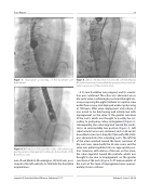
Figure 3. Appropriate positioning of the CoreValve pre- deployment.
Figure 4. Deformation of the proximal struts of CoreValve sug- gesting external impingement. Ventricular displacement of the CoreValve is seen.
wire (Cook Medical, Bloomington, IN, USA) was posi- tioned in the left ventricle to facilitate the CoreValve implantation.
Figure 5. Left tab of the CoreValve snared with a 25-mm Amplatz GooseNeck snare and valve pulled into proper position. Note ab- luminal projection of the proximal struts.
A 31-mm CoreValve was prepped, and its orienta- tion was con rmed. The valve was advanced across the aortic valve, con rming its position in the right cor- onary cusp using the pigtail catheter in coplanar view under uoroscopy, and deployed under rapid pacing at 130 bpm. After valve deployment and release, it was noted to be functioning well initially but with impingement on the valve at the greater curvature of the aorta, which was thought to possibly be sec- ondary to pulmonary artery enlargement (Figure 3). Subsequently, the valve migrated toward the ventri- cle in an unacceptably low position (Figure 3). Left radial arterial access was obtained, and a 120-cm 6-F GooseNeck snare (ev3, Amplatz, Plymouth, MN, USA), was advanced into the ascending aorta. The left tab of the valve oriented toward the lesser curvature of the aorta was snared with the 25-mm snare, and the valve was pulled cephalad into an appropriate posi- tion. However, with release of tension on the snare, the valve migrated toward the ventricle, which was thought to be due to impingement on the greater curvature of the aorta (Figure 4). CT measurements of the aorta at this level of impingement were approxi- mately 23 mm × 20 mm.
Journal of Structural Heart Disease, February 2017
Volume 3, Issue 1:28-34
