
Page 13 - Journal of Structural Heart Disease Volume 4, Issue 5
P. 13
New Technology 208
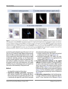
Figure 1. The three steps of motion compensation: i. Anatomical roadmap generation: (Panel A) Vascular Outlining (VO) based on the angiographic image, (Panel B) Computed-Tomography (CT) segmentation registered to the angiographic image. ii. Correlate an- atomical roadmap to pigtail catheter: (Panel C) The reference map for the pigtail is extracted, (Panel D) The spatial relation between the pigtail reference map (blue) and the anatomical roadmap (red) is set. iii. Live motion compensation: (Panel E) The pigtail reference map best matching the current pigtail shape is selected, (Panel F) Live fluoroscopic image is filtered (left) and matched to the pigtail reference map (right), (Panel G) Fluoroscopic view of the matching result, (Panel H) The transformation is applied to the anatomical roadmap resulting in a dynamic motion-compensated roadmap, either VO (blue) or CT (red).
outside the optimal depth range still occurs in 21% of the cases [4], resulting in high-degree atrioventricular block (10-30%) and paravalvular leak (4-35%) [5]. We have created a fully-automated software that enables anatomical roadmap overlays on live fluoroscopic images compensated for cardiac and respiratory mo- tion without workflow disruptions, which may allow for greater control over valve placement. This paper describes how our technology works and reports on the results of the feasibility study performed.
Method
Our algorithm comprises three steps:
i. Anatomical roadmap generation. Angiograms
with contrast injections are automatically identi- fied and the frame best opacifying the aortic root is selected by the algorithm, upon which two types
of anatomical roadmaps are generated:
1. Vascular Outlining (VO): The outline of contrast
is detected in the X-ray image (Figure 1a).
2. Computed Tomography (CT) aided: The auto- matic CT segmentation [6, 7] is registered to the
angiographic image (Figure 1b).
ii. Correlate anatomical roadmap to the pigtail
catheter. The pigtail catheter is routinely locked in an aortic valve cusp and its motion reflects overall aortic valve motion. The software searches for the pigtail catheter (Figure 1c) and sets the spatial re- lationship with respect to the anatomical roadmap (Figure 1d). This correlation process is performed for all angiograms producing a series of references (Figure 1e).
iii. Live motion compensation. Each live fluoroscop- ic image is filtered to enhance pigtail-like objects, which is then matched to the references (Figure
Journal of Structural Heart Disease, October 2018
Volume 4, Issue 5:207-211
