
Page 118 - Journal of Structural Heart Disease Volume 5, Issue 4
P. 118
Meeting Abstracts
180
AC B
D
GH
L
K
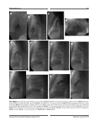
155. Figure 1. Pulmonary Valve Perforation procedure. Panel A. RVA(AP) showing the tripartite right ventricle. Panel B. RVA (lat- eral) showing the tripartite right ventricle. Panel C. Aortogram no coronary sinusoids. Panel D. Well developed pulmonary artery branches. Panel E. Simultaneous injection with one catheter at the end of the ductus and second catheter facing the pulmonary valve dimple demonstrating the site of the membrane. Panel F. A 5 mm goose neck snare to give a clear demarcation of its site. Panel G. The stiff end of the coronary wire perpendicular on the membrane. Panel H. Control hand injection noRVOT perforation. Panel I. AV loop. Panel J. A coronary balloon inf. Panel K. BPV1. Panel L. BPV2.
E
F
I
J
Journal of Structural Heart Disease, August 2019 Volume 5, Issue 4:75-205
