
Page 16 - Journal of Structural Heart Disease Volume 3, Issue 1
P. 16
9
Original Scienti c Article
Figure 1.
closure is at least as safe and e ective as anticoagu- lation with warfarin with regard to all-cause mortal- ity and stroke risk [5]. LAA-occlusion devices have a xed shape designed to provide an e ective seal and stable positioning, but this may not take into account signi cant variability in LAA shape, orientation, and structure. Furthermore, regardless of the LAA closure device used, co-axial alignment of the delivery sheath within the appendage is crucial for safe and success- ful implantation, and this depends on the orientation of the LAA. Suboptimal alignment of the delivery system within the appendage may cause perforation [5, 6] and poor nal device position, potentially pro- moting residual leaks [7] and thrombus formation. These complications remain the Achilles heel of the procedure, partially o setting its potential bene ts.
In addition, variation in LAA anatomy may in u- ence the detection of LAA thrombus during tran- soesophageal echocardiography (TOE). Thrombus located in accessory or retroverted lobes might es- cape recognition in the usual TOE views, which may partially explain the small incidence of stroke despite TOE interrogation of the LAA prior to cardioversion [8]. Hence, a good understanding of LAA anatomy
and orientation is important. Several studies have highlighted variations in LAA anatomy, particularly focusing on LAA size, branches/lobes, or ori ce di- ameter [9, 10]. Few studies, however, have described LAA orientation and shape, which are important for device and delivery system design [11, 12].
Here, we examined the range of three-dimensional (3-D) anatomy and 2-D geometry of the LAA in pa- tients with non-valvular AF to allow sheath con gu- ration and device design improvements that facilitate delivery and deployment. In addition, recognition of unusual anatomical variants may prompt clinicians to interrogate the LAA in all dimensions, which could improve thrombus detection.
Materials and Methods
Study Population
The population consisted of 103 consecutive patients with non-valvular AF who underwent left atrial and pulmonary vein (PV) angiograms using cardiovascular magnetic reso- nance (CMR) for the purpose of PV isolation ablation (94%), evaluation for possible PV stenosis after PV isolation ablation (5%), or cardiac surgery (1%). The 3-D datasets were processed to ensure good visualization of the LAA and PVs. Twenty-sev- en patients were excluded due to inadequate image quality. In the remaining 76 patients in whom the LAA was analyzed, 67% were male and 33% were female, with a mean age of 56 ± 11 years (range, 18–77 years).
CMR Scanning and Image Processing
Scans were performed using a 1.5-Tesla magnetic reso- nance scanner (Siemens Avanto, Siemens Medical Imaging, Erlangen, Germany) at the University of Oxford Centre for Clinical Magnetic Resonance Research. After obtaining local- izer images, 3-D contrast-enhanced MR angiograms were ac- quired using a spoiled gradient echo sequence in a coronal voxel positioned to include the whole left atrium and proxi- mal PVs and timed to the rst passage of gadolinium contrast in the left atrium following a test bolus of 2 mL gadolinium contrast. The sequence was acquired during a single 20–30-s breath-hold and was not ECG-gated; scan parameters: TE, 1.1 ms; TR, 3.0 ms; ip angle, 25°; FoV, 360–400 mm; slice thick- ness, 1.2 mm; 96 slices per slab (slab thickness, 115 mm); and iPAT factor, 3 (GRAPPA). Contrast enhancement was achieved with 0.15 mmol/kg body weight of gadodiamide (Omniscan®, GE Healthcare, Cleveland, OH, USA) administered via an an- te-cubital vein at 6 mL/s followed by a saline ush of 20 mL at the same injection rate. After acquisition, data were processed using Siemens Argus software to generate a 3-D surface-ren- dered image of the left atrium including the LAA. Surrounding structures, such as the aorta, right ventricle, and any residual pulmonary arteries were carefully edited out of the image. This 3-D model was used for assessment of LAA shape, orien-
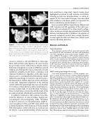
Representative left atrial appendage morphologies (three-dimensional surface rendered angiographic images). Panel A. Bi-lobed. Panel B. Fan-shaped with three small lobules. Panel C. s-con gured. Panel D. Very large fan-shaped with sec- ondary anterior lobe and multiple lobules. All images are viewed from a similar left postero-lateral position; the left atrial append- age is indicated by an asterisk (*).
Joy, S. et al.
LAA Morphology in Non-Valvular AF
