
Page 28 - Journal of Structural Heart Disease Volume 5, Issue 1
P. 28
17 Case Report
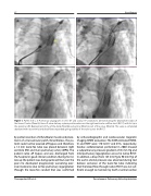
Figure 1. Panels A, B, C, D. Pulmonary angiograms in LAO 40° and cranial 15° projections demonstrating the deployment steps of the Venus P-valve. (Panel A). Venus P-valve delivery system positioned across the right ventricular outflow tract (RVOT) with its tip in the proximal LPA. Deployment of the of the distal (Panel B) and central (Panel C) part of the valve. (Panel D). The valve is completed deployed with its proximal and distal flares expanded giving stability of the valve across the RVOT.
by partial resection of infundibular muscle and place- ment of a transannular patch. Nevertheless, the pa- tient could not be weaned off bypass and therefore, a 14 mm Gore-Tex tube was placed between right ventricle (RV) and main pulmonary artery (MPA). The patient came off bypass and was discharged from the hospital in good clinical condition. During his fol- low-up the patient was doing quite well but over the years he developed progressively worsening exer- cise intolerance due to free pulmonary regurgitation through the Gore-Tex conduit that was confirmed
by echocardiographic and cardiovascular magnetic Imaging (CMR) evaluation. The CMR estimated RVED- Vi and RVEF were 170 ml/m2 and 45%, respectively. Cardiac catheterization performed in 2008 showed a subpulmonary pressure gradient of 45 mm Hg and mild pulmonary regurgitation across his native RVOT. In addition, a drop (from 125 mm Hg to 90 mm Hg) of the aortic arterial pressure was observed during test balloon occlusion of the Gore-Tex tube indicating that the blood flow through native RVOT was not suf- ficient enough to maintain by itself a normal cardiac
Thanopoulos B.D. et al.
Percutaneous Pulmonary Valve Implantation
