
Page 15 - Journal of Structural Heart Disease Volume 5, Issue 6
P. 15
239 Original Scientific Article
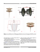
Figure 1. Konar-MFO. Panel A. The device. Panel B. The design. Panel C. Device Components Denomination: (Panel D) Disc diameter, (Panel D1): Waist Diameter Right Ventricular side (Panel D2): Waist Diameter Left Ventricular side. Panel D. The arrows show the PTFE.
"D", except for the 5-3, 7-5 and 9-7 devices where 2.5 mm must be added on each side.
Devices whose disc diameters "D" is ≥ 14 mm have a PTFE membrane inside (Figure 1).
The delivery system consists of a sheath and a ca- ble (Figure 2). The cable has a thickness of 3 fr and a length of 1,5 m. On one side it has a screw to hold the device and on the other a handle that allows the device delivery maneuver with a counter-clockwise
rotation. The delivery sheaths diameter depends on the diameter of the device (Table 1).
All procedures were performed under general an- esthesia and patients were anticoagulated with Hep- arin 100 IU / kg and repeated 50 IU / kg every hour. 7500 IU were used in adults and afterward added 2500 IU more.
Damsky Barbosa J. et al.
VSD Closure with KONAR-MFO
