
Page 32 - Journal of Structural Heart Disease Volume 2, Issue 1
P. 32
Original Research Report
26
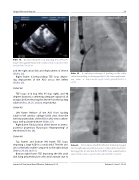
Video 34. Corresponding TEE loop depicting the LSPV tech- nique. View supplementary video at http://dx.doi.org/10.12945/j. jshd.2016.007.14.vid.34.
and the right atrial disk and deployment of device (Video 22).
Right frame: Corresponding TEE loop depict- ing deployment of the ASO across the defect (Video 23).
Slide # 42:
TEE loops at 0 (top left), 45 (top right), and 90 degrees (bottom), con rming adequate capture of all margins before releasing the device from the loading cable (Videos 24, 25, and 26, respectively).
Slide # 43:
Left frame: Release of the ASO from loading cable in left anterior oblique (LAO) view. Note the well-separated disks of the ASO in LAO view con rm- ing a well-positioned device (Video 27).
Right frame: Final position of the device in antero- posterior projection; uroscopic “ ngerprinting” of the device (Video 28).
Slide # 46:
Top frames and bottom left frame: TEE loops depicting a large ASD in a small child. The left atri- um is relatively smaller compared to the right atrium (Videos 29, 30, and 31).
Bottom right frame: TEE depicting the left atrial disk lying perpendicular to the atrial septum due to
Video 35.
A contrarian technique of pushing on the cable rather than pulling, to disengage the LA disk. View supplemen- tary video at http://dx.doi.org/10.12945/j.jshd.2016.007.14. vid.35.
Video 36.
ASO is deployed with the left atrial disk being engaged into the right superior pulmonary vein. Loading cable is pushed to disengage the let atrial disk from the RSPV. View supplementary video at http://dx.doi.org/10.12945/j.jshd.2016.007.14.vid.36.
Journal of Structural Heart Disease, February 2016
Volume 2, Issue 1:15-32
